5 Tips for 11kV to 400V Distribution Transformer
Selecting an 11kv To 400v Distribution Power Transformer is not simply a matter of changing voltage. It is a practical decision affecting safety, efficiency, maintenance, and future load growth. An 11kV incoming supply must become stable 400V power for factories, commercial buildings, pumps, and lighting systems. Small design errors can create heat, nuisance trips, or costly downtime.
Transformer specialist Dr. J. C. Das emphasizes a useful principle: “Good transformer design begins with understanding the load, not merely the voltage ratio.” That idea guides this discussion. The transformer must match real demand, including motor starting currents, harmonic-producing equipment, and uneven phase loading. Rated capacity matters. So do impedance, vector group, insulation level, tap settings, and enclosure protection. The details are physical. Think of warm oil, cable glands exposed to rain, and terminals tightened inside a crowded panel.
A reliable installation also depends on earthing, surge protection, cooling, testing, and routine inspection. Measure winding resistance. Check insulation before energizing. Inspect oil, bushings, connections, and abnormal sounds during operation. These steps are simple. They are often skipped.
The five tips ahead focus on choices that influence service life and operating confidence. They are not a substitute for local codes, manufacturer instructions, or a qualified engineer’s review. That limitation matters. A transformer selected from a spreadsheet may still fail in a dusty plant with frequent overloads. Good engineering includes calculation, site experience, and honest reconsideration when conditions change.
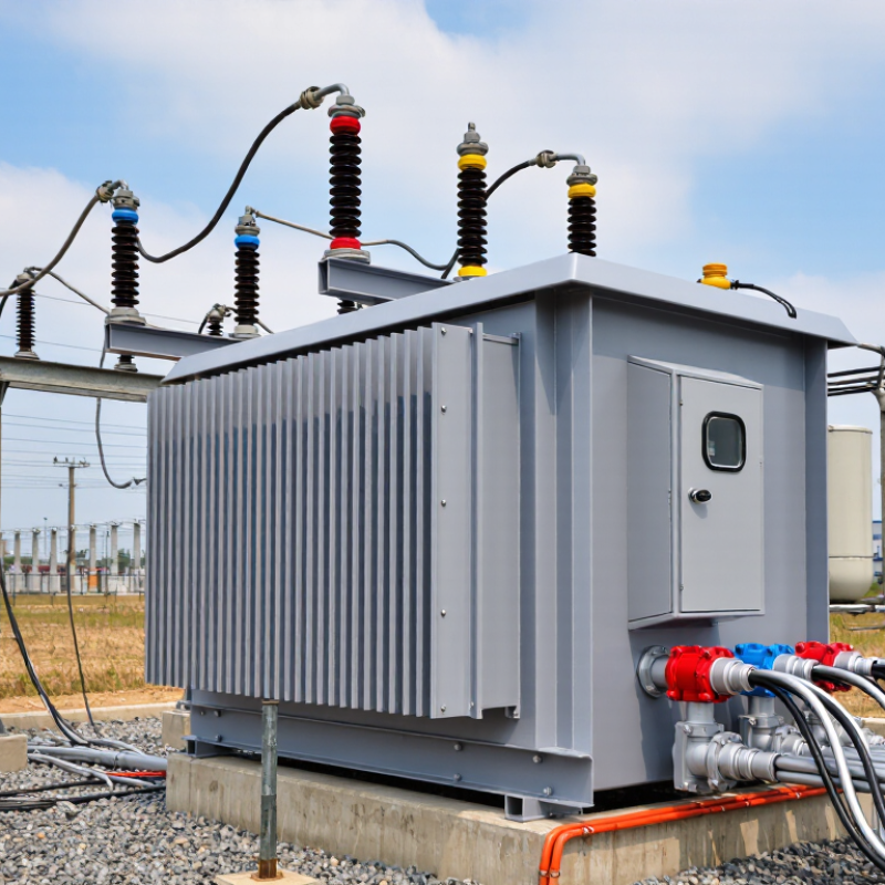
11kV to 400V Distribution Transformers: Purpose and Basic Structure
An 11kV to 400V distribution transformer reduces medium voltage to a safe, usable level for factories, commercial buildings, and local networks. Its primary winding receives 11kV, while the secondary winding delivers 400V, usually through a three-phase connection. The magnetic core transfers energy between windings without direct electrical contact. The tank contains oil or dry insulation, bushings provide external connections, and a tap changer helps correct voltage variation. IEC 60076 defines key transformer performance and testing requirements.
Tip 1: Check the actual load profile, not only the nameplate rating. A 1,000kVA unit can suffer avoidable heating when harmonics or poor power factor increase current. IEEE C57.91 provides practical guidance for oil-immersed transformer loading and temperature evaluation.
Tip 2: Treat no-load losses seriously. The transformer remains energized throughout the day. The U.S. Department of Energy’s Distribution Transformer Energy Conservation Standards analysis estimates major long-term energy savings from reducing transformer losses. Small losses become expensive over decades.
Tip 3: Specify protection with the installation environment in mind. Indoor units may need dry-type insulation, while outdoor units often require weatherproof tanks, pressure relief, and oil containment.
Tip 4: Confirm the secondary earthing arrangement before energizing.
Tip 5: Review ventilation and clearance on site. A neat drawing can still fail in a crowded electrical room. Field measurements sometimes reveal assumptions that design calculations missed.
How Voltage Reduction Works in an 11kV/400V Transformer
An 11kV/400V transformer reduces medium voltage through electromagnetic induction. The high-voltage winding receives 11,000 volts. The low-voltage winding delivers about 400 volts between phases. In a three-phase system, this also provides approximately 230 volts from phase to neutral. The turns ratio is roughly 27.5:1, so fewer secondary turns create a lower voltage.
Alternating current produces a changing magnetic flux inside the core. That flux transfers energy across the insulated windings without a direct electrical connection. Frequency must remain stable because flux depends on voltage and frequency. When load current rises, winding resistance and leakage reactance cause voltage drop. The output may therefore fall below 400 volts during heavy demand. Check it under realistic load conditions. No-load readings can mislead.
Keep the transformer properly earthed. Confirm the tap setting before energising. Taps adjust the primary winding ratio for supply variations, but they do not replace correct system design. Inspect cable terminations for heat marks, loose hardware, or moisture. Verify protection settings against the transformer rating and inrush current. Measure phase balance regularly. A small imbalance can increase heating. I once found a “normal” panel reading hiding a loose neutral connection; assumptions deserve testing. Ventilation matters too. Dust and blocked airflow can shorten insulation life, even when the measured voltage looks correct.